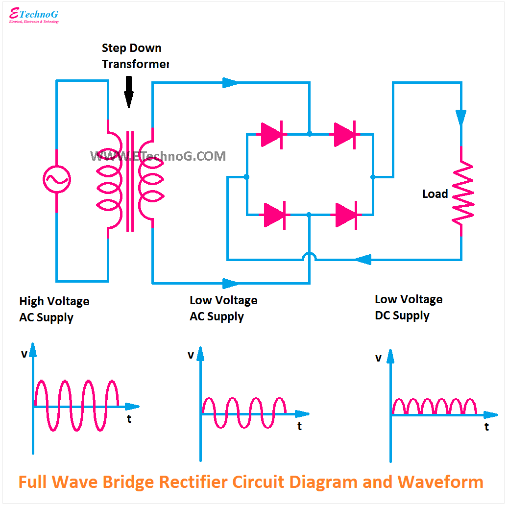
Diode Bridge Schematic Circuit Diagram Of Full Rectifier
Rectifier diode circuit diagram Why is this ideal diode bridge rectifier simulation in ltspice not Bridge rectifier – construction, working, advantages
Why is this ideal diode bridge rectifier simulation in LTSpice not
Full wave bridge rectifier download scientific diagram Rectifier capacitor resistor transcription electrical Explain full wave bridge rectifier with diagram pcb designs
Full wave bridge rectifier schematic
[solved] only problem 2! repeat problem 1 for the full-wave bridgeBridges schematic Rectifier circuit diagramIntroduction of full wave rectifier.
Rectifier schematicBridge rectifiers: what is it? (circuit diagram & working principle Bridge diode and schematic stock photo. image of spare44 diode bridge schematic diagram.

Bridge rectifier circuit, construction, working, and types
The full-wave bridge rectifierRectifier literal meaning at mary simmons blog Bridge rectifierHow does a 4 diode bridge rectifier work.
Circuit diagram of full wave bridge rectifier with capacitor filterAn introduction to rectifier circuits Bridge rectifier rectifiers principle electrical4uFull wave bridge rectifier circuit diagram.

Circuit diagram of full rectifier
How bridges are builtFull bridge rectifier circuit diagram 13+ bridge diode diagramFord f650 ignition schematic.
.


Bridge Rectifier Circuit, Construction, Working, and Types

circuit diagram of full wave bridge rectifier with capacitor filter

An Introduction To Rectifier Circuits - Riset

The Full-Wave Bridge Rectifier - Last Minute Engineers

Ford F650 Ignition Schematic

Introduction Of Full Wave Rectifier

How Does A 4 Diode Bridge Rectifier Work

44 Diode Bridge Schematic Diagram - Riset

Bridge Rectifiers: What is it? (Circuit Diagram & Working Principle